
This chapter describes how to use Keysight SD1 SFP software:
Keysight M3201A/M3202A PXIe AWGs, M3100A/M3102A PXIe Digitizers, and M3300A/M3302A PXIe AWG/Digitizer Combos can be operated as classical bench-top instruments using Keysight SD1 SFP software; no programming is required.
When SD1 SFP is opened, it identifies all Keysight PXIe hardware modules that are connected to the embedded controller or desktop computer and opens a corresponding soft front panel for each piece of hardware.
|
|
||
| SD1 SFP |
Keysight SD1 SFP Software provides a fast and intuitive way of operating Keysight M3201A/M3202A PXIe AWGs, M3100A/M3102A PXIe Digitizers, and M3300A/M3302A PXIe AWG/Digitizer Combos.
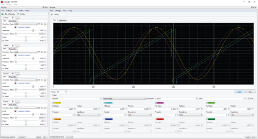
The M3201A/M3202A PXIe AWGs soft front panel appears automatically when SD1 SFP is launched and the module is connected to the chassis. If there are no modules available, SD1 SFP will launch "Demo Offline" modules.
M3201A/M3202A PXIe AWGs Soft Front Panel Controls
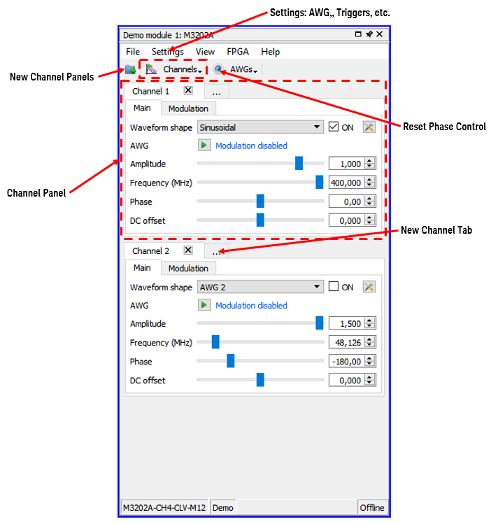
When SD1 SFP is launched, the M3201A/M3202A PXIe AWGs soft front panel appears empty, waiting for the user to add ”Channels”, which are windows that control the channel operation. For maximum visualization flexibility, output channels can be added as new Panels or as Tabs within an existing Panel.
Signal generation controls are available for the M3201A/M3202A PXIe AWGs.
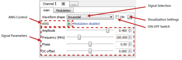
M3201A/M3202A PXIe AWGs signal generation control
AWG dialogs and the workflow to generate arbitrary waveforms is available using the AWGs.
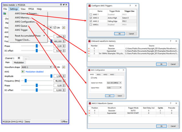
Once the waveforms are queued in the corresponding AWG, they can be launched using the AWG control button.
This tab configures the modulations.
![]()
M3201A/M3202A PXIe AWGs signal modulation control
As described in Working with Signal Modulation, the modulating signal for the modulators of one channel comes from the AWG corresponding to that particular channel. Therefore, the user must configure the AWG (See AWG workflow in SD1 SFP and the modulators). After this process, the user must run the AWG in the channel panel.
IQ modulators use both the amplitude modulator and the phase modulator. Therefore, the IQ modulator can be selected from any of the ”modulation type” combo boxes.